
Email Id: sale@adctooling.com
Global buyers are entering a faster, less forgiving Module Transceiver market. AI clusters now demand higher bandwidth, lower latency, and tighter power control. LightCounting’s recent market analyses identify 800G and emerging 1.6T optical products as major growth drivers. Dell’Oro Group also reports strong investment in AI-oriented data-center networking. The direction is clear. The details are not.
Vladimir Kozlov, founder and chief analyst at LightCounting, has emphasized, “AI is changing the optical market faster than previous cloud cycles.” Buyers should treat that warning seriously. A transceiver that performs well in a laboratory may struggle inside a dusty regional data center. Temperature, fiber type, connector cleanliness, firmware support, and replacement availability all matter. Price alone is a weak filter.
This guide examines the 2026 best Module Transceiver types for global buyers. It compares 400G, 800G, coherent, parallel-optics, and single-mode solutions across distance, power, interoperability, and total ownership cost. The analysis also considers findings from LightCounting, Dell’Oro Group, and Omdia, while recognizing that forecasts can change quickly. Some purchasing decisions remain imperfect. Specifications can look impressive, yet field results may disappoint. That is why qualified testing, supplier audits, and documented compatibility should accompany every quotation. Global procurement needs evidence, not just attractive bandwidth numbers.
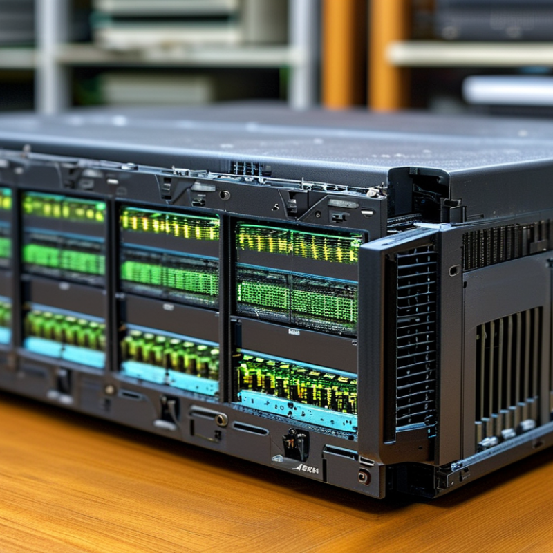
For global buyers, transceiver selection now depends on port speed, distance, power, and upgrade timing. LightCounting’s 2024 Ethernet Optics Market Update projects the optical transceiver market to exceed 20 billion dollars before 2028. Data-center expansion remains the main driver.
SFP fits mature 1G links and simple access networks. SFP28 raises capacity to 25G while keeping a compact footprint. QSFP28 supports 100G through four 25G lanes, making it practical for aggregation. These modules are easier to deploy, but older switches may limit their real performance. Check host compatibility carefully.
QSFP-DD commonly serves 400G and emerging 800G connections through multiple electrical lanes. OSFP offers stronger thermal headroom for high-speed designs, especially in dense computing systems. CDFP provides very high port density, yet its ecosystem is narrower today. The Ethernet Alliance’s 2024 technical roadmap highlights 800G and 1.6T Ethernet as active development paths. That direction matters for large-scale buyers, but it does not make every new module a wise purchase. Higher speed often means greater power draw, stricter cooling, and shorter practical reach. I would verify lane mapping, firmware support, optical budgets, and return-loss limits before ordering. Small errors become expensive at scale.
| Transceiver Family | Typical Aggregate Data Rate | Electrical Lanes | Common Ethernet Applications | Common Optical Configurations | Typical Reach Range | Primary Advantages | Main Buying Considerations |
|---|---|---|---|---|---|---|---|
| SFP | Typically 100 Mb/s to 1.25 Gb/s; some variants support 2.5 Gb/s services | 1 lane | Fast Ethernet, Gigabit Ethernet, legacy storage and telecom links | Single-mode or multimode; duplex or single-fiber bidirectional options | Approximately 100 m to 80 km, depending on wavelength, fiber, and optics | Mature ecosystem, low power consumption, broad equipment compatibility, and economical replacement | Legacy interface support, host-device compatibility, optical budget, and availability of coded modules |
| SFP28 | 10 or 25 Gb/s per port | 1 lane | 10GbE and 25GbE server, switch, storage, and telecom connections | 10G or 25G single-lambda, duplex parallel-fiber, and bidirectional variants | Approximately 70 m to 40 km, depending on multimode or single-mode design | Efficient 25G connectivity, suitable for high-density server access, and generally backward-compatible with many SFP-based ports | Actual host port speed, forward-error-correction requirements, fiber type, and interoperability at 10G or 25G |
| QSFP28 | 100 Gb/s | 4 lanes at approximately 25 Gb/s each | 100GbE leaf-spine links, data-center interconnects, and network aggregation | 4 × 25G parallel multimode or single-mode; 100G single-lambda variants also exist | Approximately 70 m to 10 km for common data-center and single-mode variants | Widely deployed 100G form factor, strong cable and optical choice, and support for breakout to 4 × 25G | Parallel-fiber polarity, FEC mode, breakout support, thermal limits, and port configuration |
| QSFP-DD | 200, 400, or 800 Gb/s, depending on electrical generation and optical design | 8 lanes; commonly 8 × 50G, 8 × 56G, or 8 × 100G signaling | 200GbE and 400GbE leaf-spine networks; 800GbE adoption in high-capacity platforms | Parallel multimode or single-mode, 2 × 200G, 4 × 100G, 8 × 50G, and single-lambda options | Approximately 30 m to 10 km for common data-center and campus interconnect designs | High bandwidth in a compact footprint, backward mechanical compatibility with many QSFP installations, and flexible breakout options | Host electrical generation, modulation format, FEC, thermal design, cable assembly, and firmware qualification |
| OSFP | 400 or 800 Gb/s; higher-rate implementations are under development | 8 lanes; commonly 8 × 50G or 8 × 100G signaling | 400GbE and 800GbE switching, artificial intelligence clusters, and high-density data-center fabrics | Parallel multimode or single-mode, 2 × 200G, 4 × 100G, 8 × 50G, and single-lambda designs | Approximately 30 m to 10 km for commonly deployed optical variants | Larger thermal envelope, high power capacity, and strong suitability for high-speed optical engines | Mechanical incompatibility with QSFP cages, host-port qualification, power class, heat dissipation, and cable bend radius |
| CDFP | Typically 400 Gb/s | 16 lanes at approximately 25 Gb/s each | Earlier-generation 400GbE demonstrations, specialized high-density switching, and selected legacy deployments | 16 × 25G parallel multimode or single-mode optical architectures | Usually short-reach data-center links up to approximately 2 km, depending on optical implementation | High lane density and an early path to 400G connectivity | Limited current ecosystem, larger connector and fiber count, higher integration complexity, and reduced long-term availability compared with newer 400G families |
Ethernet transceiver selection now spans 1G to 800G classes. Each class reflects different bandwidth, lane design, reach, and power requirements. IEEE 802.3 defines core Ethernet behavior, while MSA groups often shape practical module formats and interoperability details. Buyers should verify both references before comparing specifications.
A 1G or 10G module may suit legacy access networks and short server links. 25G and 100G options are common in modern data-center connections. Higher-speed 200G, 400G, and 800G modules usually depend on parallel lanes, advanced modulation, and stronger thermal planning.
Connector type matters too. So does fiber mode, cable length, and host port support. In real installations, a higher speed can create unexpected cooling and compatibility costs. I have seen specifications look correct, yet fail during link testing because FEC settings were overlooked. That detail deserves more attention.
Tips: Match the module to the switch port, not only the advertised speed. Check IEEE references, applicable MSA documents, lane configuration, optical budget, and operating temperature. Request test records when buying large volumes. A compatibility matrix is useful, but it is not perfect. Validate sample units in the target network before final purchasing.
Choosing a transceiver starts with distance, not marketing language. SR modules typically support about 100 meters over multimode fiber. They suit server rooms, racks, and short data-center links. DR modules commonly reach 500 meters through single-mode fiber. FR modules often cover around 2 kilometers. These ranges can vary by speed, fiber quality, and deployment conditions.
LR modules generally support links near 10 kilometers. ER modules extend reach to approximately 40 kilometers. ZR modules can approach 80 kilometers, but they demand careful engineering.
Optical loss, dispersion, connector cleanliness, and power budgets all matter. A longer-rated module is not automatically the safer choice. It may increase cost, heat, and operational complexity.
In field checks, I look beyond the printed distance. I verify the transceiver’s data rate, wavelength, fiber type, FEC support, temperature rating, and diagnostic functions. A clean 10-kilometer link can perform better than a poorly installed 2-kilometer connection. That sounds obvious, yet teams still overlook patch-panel loss. The distance ladder is useful, but imperfect. Real networks contain bends, aging connectors, and uncertain records. Buyers should leave optical margin and test the complete path before acceptance.
Application selection should begin with traffic, reach, and operating conditions, not module speed alone. In data centers, 400G and 800G modules suit short rack-to-rack links, while longer campus paths may require coherent or extended-reach optics. The IEA projects data-center electricity use could rise from about 415 TWh in 2024 to over 945 TWh by 2030. Power consumption matters. A lower-power module can reduce heat around dense switch ports, although its purchase price may be higher.
5G fronthaul needs strict timing, low latency, and stable performance over fiber links. The Ericsson Mobility Report forecasts about 5.6 billion global 5G subscriptions by the end of 2029. That growth increases pressure on distributed radio sites. Wavelength control, temperature tolerance, and precise synchronization deserve careful testing. A fast optic is not automatically a suitable fronthaul optic. Field engineers should verify dispersion, connector loss, and interoperability before large deployment.
Enterprise networks usually favor practical 10G, 25G, or 100G modules with simple replacement procedures. Telecom backbones need greater reach, monitoring, and protection against changing traffic patterns. Omdia’s optical transceiver research identifies 800G as a major expansion area, but adoption will vary by application and budget. A neat selection matrix rarely survives real sites. Firmware behavior, dust, aging fiber, and technician access can change the result. Buyers should request measured power data, temperature tests, compliance records, and independent reliability evidence.
2026 Best Module Transceiver Types for Global Buyers
Global buyers should compare more than speed and connector type. Power draw now directly affects rack economics. The IEA’s Electricity 2024 report estimates data-center demand could exceed 1,000 TWh globally by 2026. A lower-power 400G or 800G module may reduce cooling pressure. Measure watts per transmitted gigabit, not watts alone.
Digital Optical Monitoring, or DOM, provides live readings for temperature, voltage, bias current, and optical power. These values help engineers detect dirty connectors, rising temperature, or aging lasers before link failure. A 0–70°C commercial-temperature rating fits most controlled data halls. It may fail in rooftop cabinets, factory spaces, or poorly cooled edge sites. MSA compliance improves interoperability, but it does not guarantee identical firmware behavior. Verify alarms, coding, and host compatibility during testing.
Tips: Request three samples before volume purchasing. Record power at startup and steady state. Test DOM alarms under heat. Compare warranty terms, replacement stock, and technician time. Ethernet Alliance roadmaps identify 800G and 1.6T as key development paths, yet higher speed usually increases thermal demands. Total cost of ownership includes energy, cooling, downtime, optics cleaning, and replacement labor. A cheap module can become expensive. I sometimes overvalue headline bandwidth; field stability deserves equal weight.
Global buyer criteria: power efficiency, DOM capability, 0–70°C commercial ratings, MSA-aligned form factors, reach, and total cost of ownership.
| Module Type | Data Rate | Typical Reach | DOM Availability | 0–70°C Rating | TCO Position |
|---|---|---|---|---|---|
| 1G SX | 1.25 Gb/s | Up to 550 m on multimode fiber | Commonly available | Common commercial grade | Lowest entry cost |
| 10G SR | 10 Gb/s | Up to 300 m on OM3 fiber | Commonly available | Common commercial grade | Excellent short-range value |
| 10G LR | 10 Gb/s | Up to 10 km on single-mode fiber | Commonly available | Common commercial grade | Balanced distance and cost |
| 25G SR | 25.78 Gb/s | Up to 70 m on OM3 fiber | Commonly available | Common commercial grade | Strong data-center economics |
| 100G SR4 | 100 Gb/s | Up to 70 m on OM3 fiber | Commonly available | Common commercial grade | Low cost per bit at short reach |
| 100G LR4 | 100 Gb/s | Up to 10 km on single-mode fiber | Commonly available | Common commercial grade | Higher power, lower fiber complexity |
| 400G DR4 | 400 Gb/s | Up to 500 m on single-mode fiber | Commonly available | Common commercial grade | High initial cost, strong capacity efficiency |
The chart uses representative maximum power levels and standardized optical reach values for widely deployed module classes. DOM is generally available through digital diagnostic monitoring, while commercial 0–70°C versions and MSA-defined form factors are widely used. For TCO decisions, buyers should evaluate module price together with fiber infrastructure, switch-port density, energy consumption, cooling, replacement availability, and expected upgrade cycles.