What Is PTFE Lined Pipe and How Does It Work?

A ptfe lined pipe combines a strong outer pipe with a chemically resistant PTFE inner layer. The metal shell provides structural support, while PTFE forms the wetted surface. This design helps transport acids, solvents, corrosive liquids, and high-purity fluids with reduced contamination risk. It is common in chemical processing, pharmaceuticals, food production, and semiconductor facilities.

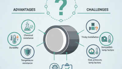
The operating principle is straightforward, but the engineering details matter. Fluid contacts the PTFE liner instead of the steel, stainless steel, or alloy pipe. PTFE resists many aggressive chemicals because of its stable carbon-fluorine structure. The lining also offers a smooth surface, which can reduce deposits and simplify cleaning. However, it does not make every piping system automatically safe. Temperature, pressure, vacuum conditions, chemical concentration, and permeation must be checked together. No lining lasts forever.

Reliable selection begins with verified data. Engineers should review chemical compatibility charts, operating temperatures, pressure ratings, flange design, and manufacturer test records. A small liner defect can expose the backing pipe and create serious maintenance problems. Installation quality matters too. Misaligned flanges, excessive bolt torque, or poor support can damage the PTFE layer. This article explains the pipe’s construction, working behavior, advantages, limitations, and inspection needs. It also questions a common assumption: chemical resistance alone is not enough. Proper design depends on the complete service environment, not one impressive material property.
What Is PTFE Lined Pipe and How Does It Work?

PTFE-Lined Pipe: Structure, Materials, and Typical 3–5 mm Lining Thickness

What Is PTFE Lined Pipe and How Does It Work?

PTFE-lined pipe combines a metal pressure shell with a seamless fluoropolymer tube. The outer shell carries mechanical loads, while PTFE isolates the process fluid. Steel provides stiffness. PTFE provides chemical resistance and a low-friction surface.

ASTM D792 places unfilled PTFE density near 2.14–2.20 g/cm³, reflecting its relatively heavy, solid structure. ISO 13000-1 and ISO 13000-2 also define key requirements for PTFE materials and semi-finished products.

In practice, the liner is flared over the pipe ends, creating a protected sealing face for gaskets and connected equipment.

A 3–5 mm lining thickness is common for many industrial pipe sizes. It offers a practical balance between abrasion allowance, flexibility, and internal diameter. That number is not universal. Actual selection depends on temperature, pressure cycling, particle loading, and vacuum conditions.

Industry technical data commonly place PTFE service temperatures around −40°C to 260°C, but pressure capability falls as temperature rises. ASME B16.5 governs flange dimensions and pressure classes, not the liner’s chemical lifetime.

A 3 mm liner may perform well in clean chemical transfer, yet erode faster in slurry service. I would not treat thickness alone as proof of reliability. Installation quality, support spacing, and inspection records often matter just as much. Even a small wrinkle can concentrate stress.
How PTFE Forms a Chemical Barrier Across a Service Range of −200 to 260°C

What Is PTFE Lined Pipe and How Does It Work?

How PTFE Forms a Chemical Barrier Across a Service Range of −200 to 260°C

A PTFE lined pipe combines a strong outer pipe with a chemically resistant inner layer. The outer shell carries pressure and protects the assembly. The PTFE lining contacts the process fluid, keeping it away from metal surfaces. This design helps prevent corrosion, contamination, and product discoloration.

PTFE remains stable against many acids, alkalis, solvents, and aggressive process chemicals. Its useful service range can extend from −200 to 260°C, depending on pressure, chemical concentration, and lining construction. At very low temperatures, PTFE stays functional but may become less flexible. At elevated temperatures, creep and permeation require careful engineering. The temperature range is impressive, but it is not a permission slip.

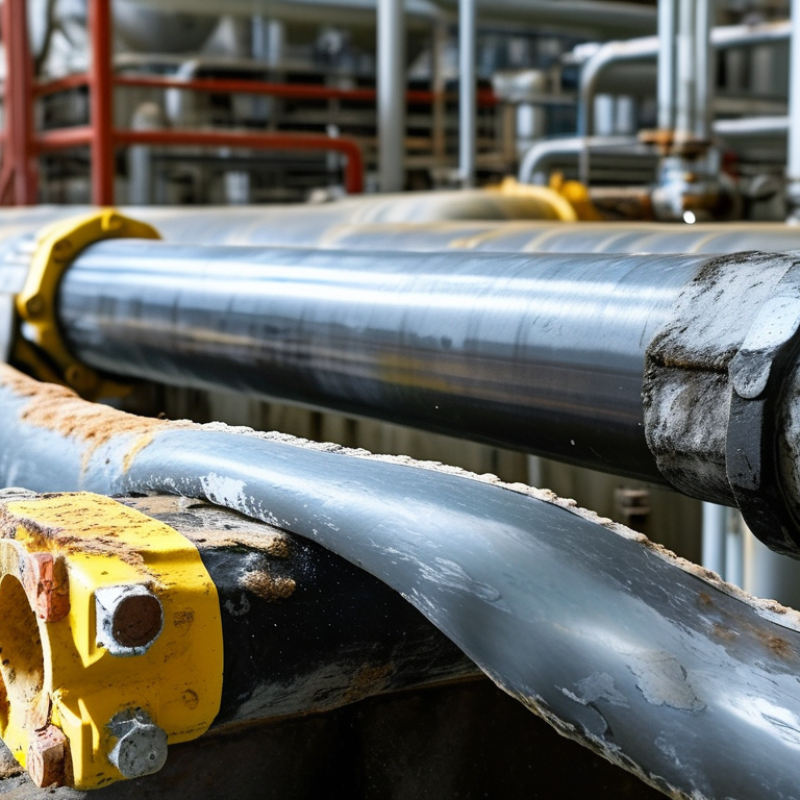
During operation, the fluid touches PTFE rather than steel. Flanged connections use lined faces, gaskets, or carefully controlled sealing surfaces. Small installation errors can expose metal at the joint. That detail matters. Thermal cycling may also create stress between the lining and the outer pipe. Designers should review vacuum conditions, pressure changes, flow velocity, and expansion behavior before selecting a system.

In field inspections, I would check flange faces, vent holes, and signs of blistering. A visual inspection cannot reveal every weakness. Electrical spark testing may identify pinholes, while thickness checks can support maintenance decisions. I have seen specifications focus heavily on temperature and overlook pressure cycling. That is an avoidable gap. Proper installation records and periodic inspection make the chemical barrier more dependable.

Pipe Manufacturing: Sintering, Flanging, and Adhesion-Free Liner Installation

PTFE lined pipe combines a strong outer pipe with a chemically resistant PTFE liner. The outer pipe carries pressure and mechanical loads. The liner protects the flow path from acids, solvents, salts, and other aggressive media. It works without relying on an adhesive layer, which can weaken under heat or chemical exposure.

Manufacturing starts with carefully prepared PTFE powder. The powder is compacted into a tube, then heated in a controlled furnace during sintering. This step fuses the particles into a dense, continuous liner. Temperature control matters. Excess heat may distort dimensions, while insufficient heat can leave weak areas. Cooling also requires patience.

The finished liner is inserted into the prepared pipe shell. Technicians check its fit, surface condition, and length before flanging the ends over the pipe faces. The flared PTFE creates a sealing surface around the opening. Bolted connections then compress this surface against a gasket or mating flange. No glue is used. That is the point.

A small clearance may be intentional. PTFE expands more than steel when heated, so the design must allow movement without buckling. In practice, poor alignment can still cause wrinkles or uneven flange contact. Visual checks, dimensional measurements, and pressure testing help reveal these problems. The process seems simple, but installation quality often decides service life.

Flow Performance: PTFE’s Typical 0.05–0.10 Coefficient of Friction

What Is PTFE Lined Pipe and How Does It Work?

A PTFE lined pipe combines a strong outer shell with a chemically resistant fluoropolymer liner. The shell carries mechanical loads, while the liner protects the process fluid from corrosion and contamination. During operation, the smooth PTFE surface reduces wall interaction with liquids, slurries, and some gases. Its typical coefficient of friction is often reported between 0.05 and 0.10 under controlled conditions, according to material data associated with ASTM D1894 testing.

The number is useful. It is not a complete pipe-flow prediction. ASTM D1894 measures friction between material surfaces, while process engineers calculate pressure loss using the Darcy-Weisbach method. Perry’s Chemical Engineers’ Handbook identifies velocity, viscosity, density, pipe diameter, and surface roughness as major flow variables. A PTFE liner can therefore support low resistance, but the final pressure drop still depends on fittings, temperature, joints, and liner condition. That distinction matters.

In field applications, operators often watch differential-pressure gauges before trusting a specification sheet. A clean liner may maintain smooth flow around bends, but deposits can change performance quickly. Higher temperatures can also soften PTFE and alter dimensional stability. I would avoid treating 0.05 as guaranteed friction in every service. The value is a reference point, not a promise. Proper design should verify the liner’s temperature rating, velocity limits, permeation behavior, and compatibility with the actual chemicals. Small installation errors matter. Misaligned flanges may create turbulence, local stress, or premature liner damage.

What Is PTFE Lined Pipe and How Does It Work? - Flow Performance: PTFE’s Typical 0.05–0.10 Coefficient of Friction

Performance Dimension Typical Value or Range How It Relates to PTFE-Lined Pipe
Coefficient of Friction Approximately 0.05–0.10 PTFE has a very low sliding coefficient of friction, which helps reduce wall drag and supports smoother movement of many liquids, slurries, and gases.
Lining Material Polytetrafluoroethylene (PTFE) The PTFE layer forms a chemically resistant internal barrier between the process medium and the structural pipe shell.
Typical Lining Thickness About 2–5 mm Actual thickness depends on pipe size, construction method, pressure requirements, and the service specification.
Continuous Service Temperature Commonly up to about 260°C (500°F) The practical limit depends on pressure, thermal cycling, lining design, and the specific PTFE formulation. Mechanical strength decreases as temperature rises.
Lower Temperature Capability Generally suitable below −50°C (−58°F) PTFE remains usable at very low temperatures, although the complete pipe assembly must also be checked for thermal contraction and mechanical stresses.
Chemical Resistance Very high for most acids, bases, and solvents PTFE resists a broad range of corrosive chemicals, but compatibility must still be verified for strong alkali metals, elemental fluorine, and certain high-temperature reactive media.
Water Absorption Less than 0.01% by weight The low moisture uptake helps maintain dimensional stability and limits water-related changes in the lining.
Surface Character Non-stick and low-energy surface The smooth, non-stick bore can reduce product adhesion and make the pipe easier to drain or clean in many process applications.
Electrical Resistivity Typically greater than 1018 ohm·cm PTFE is an excellent electrical insulator. Static-control measures may be required when handling flammable fluids, powders, or gases.
Pipe Construction PTFE liner with an outer structural shell The liner provides corrosion resistance while the external shell supplies much of the mechanical strength, pressure support, and connection geometry.
Common Structural Shell Materials Carbon steel, stainless steel, or other metals The shell material is selected according to pressure, temperature, external environment, weight, and installation requirements.
Pressure Capability Application-specific Allowable pressure is governed by pipe diameter, shell design, liner construction, temperature, flange rating, vacuum conditions, and applicable engineering standards.
Vacuum Service Requires a dedicated vacuum-rated design PTFE can deform or collapse under unsuitable external pressure. Vacuum service should be confirmed using the manufacturer’s design data and operating temperature.
Flow-Performance Benefit Reduced wall friction and lower adhesion tendency These characteristics can help limit deposits and pressure loss, but actual flow performance also depends on viscosity, velocity, pipe diameter, fittings, and surface condition.
Dimensional Stability Affected by thermal expansion and creep PTFE expands more with temperature than most metals and can slowly deform under sustained load, so liner design and operating limits are important.
Typical Applications Chemical, pharmaceutical, semiconductor, and process-fluid systems Typical services include corrosive chemicals, high-purity fluids, aggressive solvents, and products where low adhesion or easy cleaning is valuable.

Note: Values are typical engineering ranges rather than universal design limits. Final selection should be based on the exact chemical composition, concentration, temperature, pressure, flow conditions, vacuum requirements, and applicable piping standards.

Design Limits: Pressure, Permeation, Thermal Cycling, and Vacuum Resistance

PTFE lined pipe uses a corrosion-resistant fluoropolymer tube inside a metal pressure shell. The liner protects the process fluid from steel. The shell carries most of the mechanical load. Its design limit is not a single pressure number. Temperature, liner thickness, flange construction, and pipe diameter all matter. As temperature rises, PTFE softens and loses stiffness. A rating that seems safe at room temperature may become unsuitable near the upper service range. Always check the actual pressure-temperature curve.

Permeation is another quiet concern. Some gases and solvents can migrate through PTFE, even when the liner remains chemically stable. The permeated fluid may collect between the liner and shell, causing blistering or flange leakage. Thermal cycling creates a different problem. PTFE expands more than metal, so repeated heating and cooling can produce wrinkles, gaps, or loosened flares. Slow temperature changes help, but they do not remove the risk. Vacuum service requires special attention. External pressure can collapse the liner when the shell cannot support it. A vacuum-rated design, shorter unsupported lengths, and proper venting may be necessary. I would not approve vacuum operation from a pressure rating alone. That shortcut is easy to regret. Field checks should include flange faces, liner movement, discoloration, and unexpected pressure loss. Small visual changes can be early warnings.